개요
이 레슨에서는 학생들이 아두이노 학습 키트를 사용하여 디지털 알람 시계를 만드는 방법을 배웁니다. 이 키트에는 DS1307 RTC, 버저, 버튼 스위치 및 LCD 디스플레이가 포함되어 있으며, 학생들은 점퍼 와이어를 사용하여 이 구성 요소를 아두이노에 연결한 후 코드를 작성하고 업로드합니다.
학습 목표
이 레슨을 완료한 후 학생들은 다음을 배웁니다:
- I2C 통신 프로토콜에 대해 이해하고, 아두이노에서 이를 구현하는 방법.
- DS1307 RTC와 LCD 디스플레이를 인터페이스하는 방법.
- 아두이노와 버저를 사용하여 톤을 생성하는 방법.
- 아두이노 IDE에서 외부 라이브러리를 사용하는 방법.
- 프로그램에서 조건문과 루프를 사용하는 방법.
사전 요구 사항
- 아두이노 디지털 출력에 대한 기본 지식 (예: LED 제어 방법).
- 아두이노 디지털 입력에 대한 기본 지식 (예: 버튼 스위치 인터페이스 방법).
중요한 질문
- 임베디드 시스템에서 사용되는 다양한 통신 프로토콜은 무엇인가요?
- 직렬 통신과 병렬 통신의 차이점은 무엇인가요?
- 아두이노에서 사용되는 가장 일반적인 직렬 프로토콜은 무엇인가요?
- RTC가 마이크로컨트롤러 시스템에서 사용되는 이유는 무엇인가요?
필요한 재료
- 아두이노 학습 키트 및 USB 케이블
- 12개의 수-수 점퍼 와이어
- 2개의 수-암 점퍼 와이어
- PC 접속
배경 지식
I2C 직렬 통신
I2C (Inter-Integrated Circuit) 프로토콜은 여러 "슬레이브" 디지털 집적 회로("칩")가 하나 이상의 "마스터" 칩과 통신할 수 있도록 하는 프로토콜입니다. 이 프로토콜은 두 개의 와이어만으로 최대 128개의 장치 (7비트 주소 사용 시) 또는 최대 1024개의 장치 (10비트 주소 사용 시)와 통신할 수 있어 매우 인기가 있습니다.
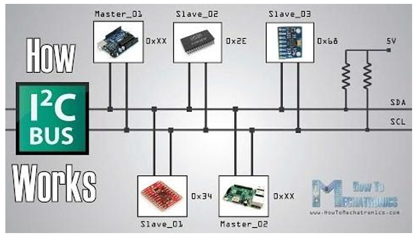
프로토콜 세부 사항
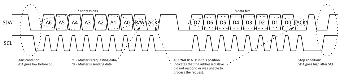
- 주소 프레임: 마스터가 슬레이브 장치를 지정하고 읽기 또는 쓰기 작업 여부를 나타냅니다.
- 데이터 프레임: 실제 전송되는 데이터를 포함합니다.
- 시작/종료 조건: 통신 시퀀스의 시작과 종료를 정의합니다.
실습 단계
- 구성 요소 연결
- DS1307 RTC, 버저, 버튼 스위치 및 LCD 디스플레이를 아두이노에 점퍼 와이어로 연결합니다.
- 코딩
- RTC를 관리하고, LCD에 시간을 표시하며, 버저를 사용하여 알람 소리를 생성하는 아두이노 코드를 작성합니다.
코드 예시
#include <Wire.h>
#include <LiquidCrystal_I2C.h>
#include <RTClib.h>

RTC_DS1307 rtc;
LiquidCrystal_I2C lcd(0x27, 16, 2);

void setup() {
  Wire.begin();
  rtc.begin();
  lcd.begin();
  lcd.backlight();

  if (!rtc.isrunning()) {
    rtc.adjust(DateTime(F(__DATE__), F(__TIME__)));
  }
}

void loop() {
  DateTime now = rtc.now();
  lcd.setCursor(0, 0);
  lcd.print(now.hour());
  lcd.print(':');
  lcd.print(now.minute());
  lcd.print(':');
  lcd.print(now.second());

  // 알람 기능을 위한 로직 추가
데이터 프레임 (Data Frames)
주소 프레임이 전송된 후, 데이터 전송이 시작됩니다. 마스터는 일정한 간격으로 클럭 펄스를 생성하고, R/W 비트에 따라 마스터 또는 슬레이브가 데이터를 SDA에 전송합니다. 데이터 프레임의 수는 임의이며, 대부분의 슬레이브 장치는 내부 레지스터를 자동으로 증가시켜 연속적인 읽기 또는 쓰기를 수행할 수 있습니다.
정지 조건 (Stop Condition)
모든 데이터 프레임이 전송된 후, 마스터는 정지 조건을 생성합니다. 정지 조건은 SCL이 높은 상태에서 SDA가 0->1(낮음에서 높음)으로 전환될 때 정의됩니다. 정상적인 데이터 쓰기 작업 중에는 SCL이 높을 때 SDA의 값이 변경되지 않아야 합니다.
DS1307 RTC
실시간 시계 (RTC)는 현재 시간을 기록하는 시스템으로, 전원이 끊겨도 정확한 시간을 유지할 수 있습니다. DS1307 모듈은 가장 저렴하고 일반적인 RTC 모듈 중 하나로, 초, 분, 시간, 일, 월, 연도를 정확하게 기록할 수 있습니다. DS1307은 I2C 인터페이스를 사용하는 8핀 장치로, 저전력 시계/캘린더 기능을 제공하며 56바이트의 배터리 백업 SRAM을 포함하고 있습니다.
주요 특징
- 배터리 백업: 전원이 끊겨도 시계/캘린더를 계속 작동할 수 있습니다.
- 정확한 시간 기록: 초, 분, 시간, 일, 월, 연도를 기록합니다.
- 자동 조정: 각 월의 마지막 날짜를 자동으로 조정합니다.
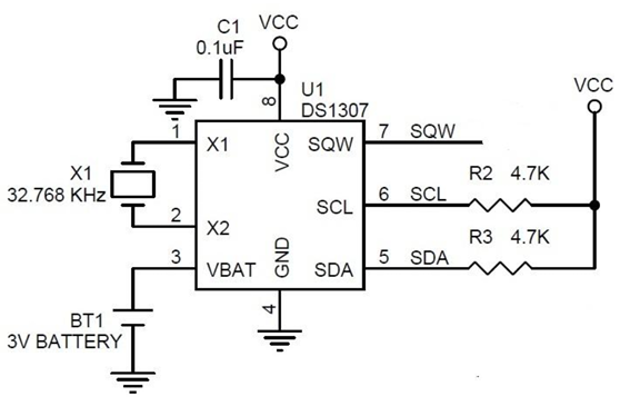
핀 아웃 및 연결
DS1307 RTC 모듈은 총 8개의 핀으로 외부와 연결됩니다. 간단한 회로에서는 두 입력 X1과 X2가 32.768 kHz 크리스탈 오실레이터에 연결되며, VBAT는 3V 배터리의 양극 단자에 연결됩니다. Vcc는 I2C 인터페이스에 전원을 공급하며, 마이크로컨트롤러를 사용하여 5V를 제공합니다. 데이터 통신은 SCL과 SDA 핀을 사용하여 아두이노와 수행됩니다. 이 두 핀은 4.7KΩ 저항으로 풀업해야 합니다.
| SCL | 아두이노 A5 (5V) |
| SDA | 아두이노 A4 (GND) |
| VCC | 아두이노 5V |
| GND | 아두이노 GND |
LCD 디스플레이
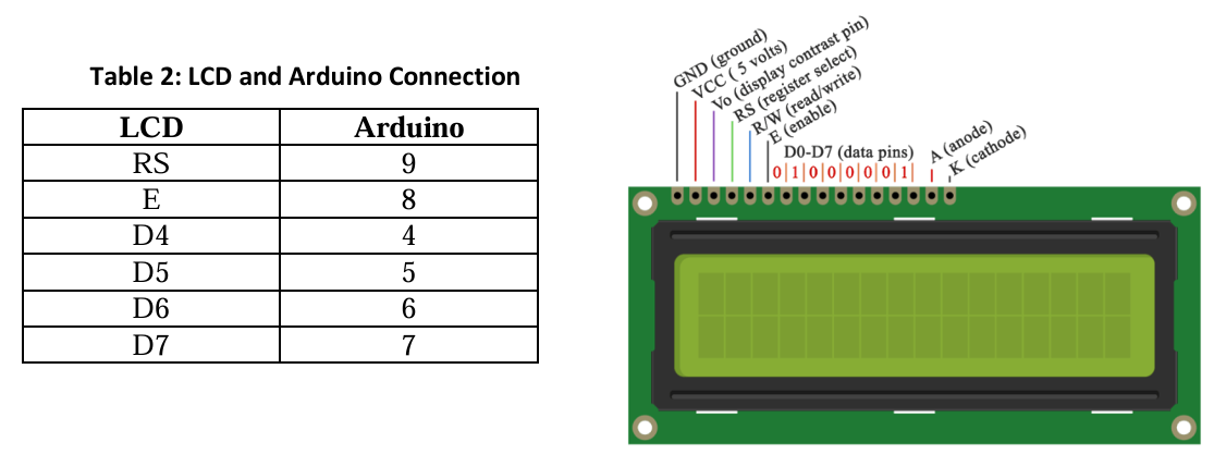
LCD(액정 디스플레이)는 정보 표시를 위한 저렴한 전자 프로젝트에서 널리 사용됩니다. 키트에 포함된 LCD는 16개의 핀이 있으며, 첫 번째 핀은 그라운드(GND) 핀입니다. 두 번째 핀은 VCC로 아두이노 보드의 5V 핀에 연결됩니다. Vo 핀에는 디스플레이의 대비를 조절할 수 있는 포텐셔미터를 연결할 수 있습니다.
- RS 핀: 명령 또는 데이터를 LCD에 전송할지 선택합니다. 낮은 상태(0V)에서는 명령을, 높은 상태(5V)에서는 데이터를 전송합니다.
- E 핀: 레지스터에 쓰기를 활성화합니다.
- D0-D7 핀: 데이터 핀입니다.
- A와 K 핀: LED 백라이트용입니다.
LCD는 4비트 모드와 8비트 모드 모두 작동할 수 있습니다. 4비트 모드에서는 D4-D7만 아두이노에 연결되며, D0-D3는 연결하지 않아도 됩니다. 키트에서는 GND, VCC, Vo, A, K가 이미 적절한 소스에 연결되어 있습니다.
절차
- 버저 연결: B_CONN(버저) 핀을 남성-여성 점퍼 와이어를 사용하여 아두이노의 D11 핀에 연결합니다.
- LCD 핀 연결: 남성-남성 점퍼 와이어를 사용하여 표 2에 따라 LCD 핀을 아두이노 핀에 연결합니다.
- 버튼 스위치 연결: S1, S2, S3, S4 핀을 아두이노 헤더의 A0, A1, A2, A3 핀에 각각 연결합니다.
- I2C 연결: SCL 핀을 아두이노 헤더의 A5 핀에, SDA 핀을 아두이노 헤더의 A4 핀에 연결합니다.
- 코드 작성: 아두이노 IDE를 열고 제공된 코드를 새로운 스케치에 복사한 후 저장합니다.
- 업로드: USB 케이블을 사용하여 키트를 PC에 연결하고 제공된 스케치를 키트에 업로드합니다.
- 시간 및 날짜 표시: 디스플레이에 시간과 날짜가 표시됩니다.
- 시간 및 날짜 조정: 버튼을 사용하여 시계의 날짜와 시간을 조정합니다.
라이브러리 설치
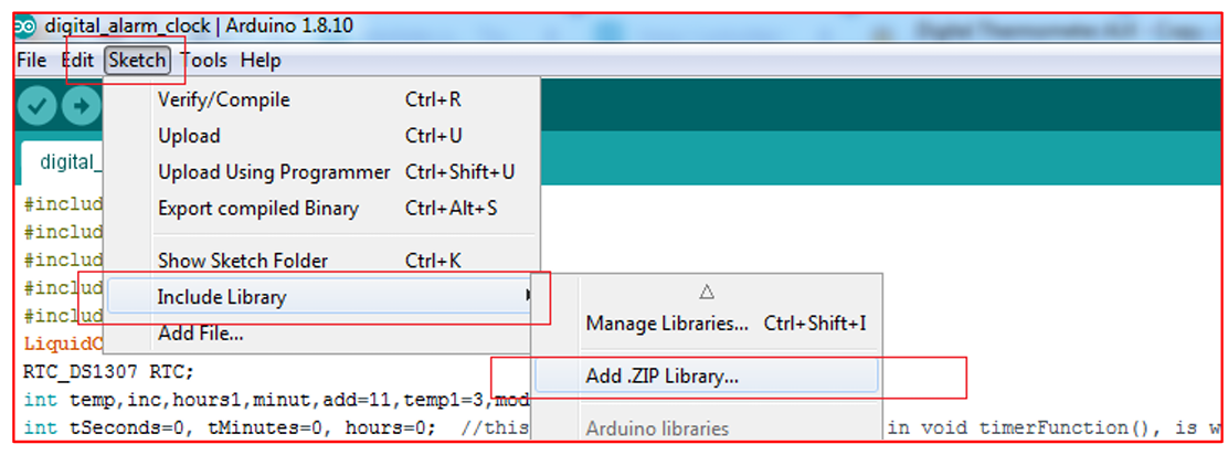
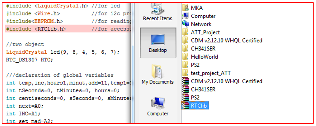
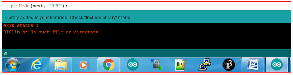
DS1307 RTC 모듈을 위한 서드파티 라이브러리를 사용합니다. 이를 위해 라이브러리를 다운로드하여 아두이노 환경에 추가해야 합니다. 다음 링크에서 라이브러리를 다운로드합니다: RTClib GitHub. ZIP 파일을 다운로드한 후, 파일 이름에 공백이나 하이픈이 포함되어 있다면 이름을 변경합니다. 아두이노 IDE에서 Sketch 메뉴로 이동하여 "Include Library"를 선택한 다음 "Add .ZIP Library"를 선택합니다. 다운로드한 .zip 파일을 찾아 추가합니다. 이제 라이브러리를 사용할 준비가 되었습니다.
link: https://github.com/adafruit/RTClib
GitHub - adafruit/RTClib: A fork of Jeelab's fantastic RTC Arduino library
A fork of Jeelab's fantastic RTC Arduino library. Contribute to adafruit/RTClib development by creating an account on GitHub.
github.com
///including the library
#include <LiquidCrystal.h> //for lcd
#include <Wire.h>          //for i2c protocol
#include<EEPROM.h>         //for reading/writing in eeprom
#include <RTClib.h>        //for accessing rtc

//two object
LiquidCrystal lcd(9, 8, 4, 5, 6, 7);
RTC_DS1307 RTC;

///declaration of global variables
int temp,inc,hours1,minut,add=11,temp1=3,mode=0;
int tSeconds=0, tMinutes=0, hours=0;
int centiseconds=0, sSeconds=0, sMinutes=0;
int next=A0;
int INC=A1;
int set_mad=A2;
int shw_dat=A3;
int buzzer=11;
int HOUR,MINUT,SECOND=0;


void setup(){
  Wire.begin(); //initilize i2c module
  RTC.begin();  //initilize rtc module
  lcd.begin(16,2); //initilize lcd
  //buttons pin as input
  pinMode(INC, INPUT);
  pinMode(next, INPUT);
  pinMode(set_mad, INPUT);
  pinMode(shw_dat, INPUT);
  //buzzer pin as output
  pinMode(buzzer, OUTPUT);
  //initilize buttons state high
  digitalWrite(next, HIGH);
  digitalWrite(set_mad, HIGH);
  digitalWrite(INC, HIGH);
  digitalWrite(shw_dat, HIGH);

   lcd.setCursor(0,0);
   lcd.print("Real Time Clock");
   lcd.setCursor(0,1);
   lcd.print("Instructable class");
   delay(3000);

Subject: Electronics, Programming                                                                                     Grade Levels: 9th-12th
Prepared By: Md. Khairul Alam
   //if rtc works then set date time ot the rtc as your pc time
   if(!RTC.isrunning())
      {
          RTC.adjust(DateTime(__DATE__,__TIME__));
      }
}

void loop()
{

   int temp=0,val=1,temp4;
   //read current date time
   DateTime now = RTC.now();


   if(digitalRead(shw_dat) == 0)
       {mode++;}

   if(digitalRead(shw_dat) == 0 && mode==1)     //set Alarm time
   {
     lcd.setCursor(0,0);
     lcd.print("    SET ALARM ??    ");
     delay(2000);

     while(1)
       {  if(digitalRead(set_mad) == 0)
         {
            time();
            delay(1000);
            lcd.clear();
            lcd.setCursor(0,0);
            lcd.print(" ALARM TIME SET ");
            lcd.setCursor(9,1);
            lcd.print(HOUR=hours1,DEC);
            lcd.print(":");
            lcd.print(MINUT=minut,DEC);
            lcd.print(":");
            lcd.print(SECOND=now.second(),DEC);
            CheckTime();
            delay(1000);
          }
        if(digitalRead(shw_dat) == 0)
        break;
      }
   }

  if(digitalRead(shw_dat) == 0 && mode==3)      //set CLOCK TIME
Subject: Electronics, Programming                                                                                     Grade Levels: 9th-12th
Prepared By: Md. Khairul Alam
   {
     lcd.clear();
     lcd.setCursor(0,0);
     lcd.print("    SET TIMER     ");
     while(1)
       {
         if(digitalRead(set_mad) == 0)
         {
            timerFunction();
         }
        if(digitalRead(INC) == 0)
            break;
       }
   }

  if(digitalRead(shw_dat) == 0 && mode==4)      //set Stopwatch
   {
     lcd.clear();
     lcd.setCursor(0,0);
     lcd.print("    STOPWATCH     ");

     while(1)
       {
         if(digitalRead(set_mad) == 0)
           {
             stopwatchFunction();
           }
         if(digitalRead(INC) == 0)
            break;
       }

   }


  if(mode>=5)
      {mode=0;}

  lcd.clear();  //refress lcd
  lcd.setCursor(0,0); //write in first line hh:mm:ss
  lcd.print(HOUR=now.hour(),DEC);
  lcd.print(":");
  lcd.print(MINUT=now.minute(),DEC);
  lcd.print(":");
  lcd.print(SECOND=now.second(),DEC);

  lcd.setCursor(0,1);  //write in second line dd/mm/yyyy
  lcd.print(now.day(),DEC);
Subject: Electronics, Programming                                                                                     Grade Levels: 9th-12th
Prepared By: Md. Khairul Alam
  lcd.print("/");
  lcd.print(now.month(),DEC);
  lcd.print("/");
  lcd.print(now.year(),DEC);

  delay(1000); //wait some time
}

/*Function to set alarm time and feed time into Internal
eeprom*/
void time()
{
  int temp=1,minuts=0,hours=0,seconds=0;
    while(temp==1)
     {
     if(digitalRead(INC)==0)
       {
        HOUR++;
        if(HOUR==24)
          {
             HOUR=0;
          }
        while(digitalRead(INC)==0);
        }
     lcd.clear();
     lcd.setCursor(0,0);
     lcd.print("Set Alarm Time ");

     lcd.setCursor(0,1);
     lcd.print(HOUR);
     lcd.print(":");
     lcd.print(MINUT);
     lcd.print(":");
     lcd.print(SECOND);
     delay(100);
     if(digitalRead(next)==0)
       {
        hours1=HOUR;
        EEPROM.write(add++,hours1);
        temp=2;
        while(digitalRead(next)==0);
       }
    }
    while(temp==2)
     {
       if(digitalRead(INC)==0)
         {
Subject: Electronics, Programming                                                                                     Grade Levels: 9th-12th
Prepared By: Md. Khairul Alam
           MINUT++;
           if(MINUT==60)
             {MINUT=0;}
           while(digitalRead(INC)==0);
         }

      lcd.setCursor(0,1);
      lcd.print(HOUR);
      lcd.print(":");
      lcd.print(MINUT);
      lcd.print(":");
      lcd.print(SECOND);
      delay(100);
      if(digitalRead(next)==0)
        {
         minut=MINUT;
         EEPROM.write(add++, minut);
         temp=0;
         while(digitalRead(next)==0);
        }
    }
    delay(1000);
}
/* Function to chack medication time */
void CheckTime()
{
  int tem[17];
  while(1)
  {
    DateTime now = RTC.now();
    lcd.setCursor(0,1);
    lcd.print(HOUR=now.hour(),DEC);
    lcd.print(":");
    lcd.print(MINUT=now.minute(),DEC);
    lcd.print(":");
    lcd.print(SECOND=now.second(),DEC);
    for(int i=11;i<17;i++)
      {
        tem[i]=EEPROM.read(i);
      }
    if(HOUR == tem[11] && MINUT == tem[12])
     {
       for(int j=0;j<5;j++)
        {
          digitalWrite(buzzer, HIGH);
          delay(500);
          digitalWrite(buzzer, LOW);
Subject: Electronics, Programming                                                                                     Grade Levels: 9th-12th
Prepared By: Md. Khairul Alam
          delay(500);
        }
    hours1=0;
    minut=0;
    add=11;
    return;
   }
  }
}

void timerFunction()  //the timer function was made with the
//help of this post: http://pastebin.com/f57045830
{
  int set=0;
    lcd.setCursor(4,1);
    lcd.print("00:00:00");
    while(1)
           {

                   while(digitalRead(shw_dat)==1)
                    {
                      set=1;
                   if(digitalRead(set_mad)==0)  //if
//"Start/Stop" is pressed, the timer counts down
                      {
                        tSeconds++;
                        lcdOutput();
                        delay(300);
                        if(tSeconds==60)
                        {
                        tMinutes++;
                        tSeconds=0;
                        }
                       }
                 if(digitalRead(INC)==0)  //if "Start/Stop" is
//pressed, the timer counts down
                      {
                        tMinutes++;
                        lcdOutput();
                        delay(300);
                        if(tMinutes==60)
                        {
                        hours++;
                        tMinutes=0;
                        }
                      }
                  if(digitalRead(next)==0 )  //if "Start/Stop"
Subject: Electronics, Programming                                                                                     Grade Levels: 9th-12th
Prepared By: Md. Khairul Alam
//is pressed, the timer counts down
                  {
                        hours++;
                        lcdOutput();
                        delay(300);
                        if(hours==24)
                        {
                        hours=0;
                        }
                  }      }
    if(digitalRead(shw_dat)==0 && set==1)
      {
       lcd.clear();
       lcd.setCursor(0,0);
       lcd.print(" TIMER SET FOR  ");
       lcd.setCursor(4,1);

       lcd.print("00:00:00");
            while(digitalRead(INC)==1)
            {
            static unsigned long lastTick = 0;
              if (tSeconds > 0)
                {
                if (millis() - lastTick >= 1000)
                {
                lastTick = millis();
                tSeconds--;
                lcdOutput();
                }
                }
            if (tMinutes > 0)
               {
              if (tSeconds <= 0)
              {
                tMinutes--;
                tSeconds = 60;
              }
              }
            if (hours > 0)
              {
              if (tMinutes <= 0)
              {
                hours--;
                  tMinutes = 60;
                }
              }

Subject: Electronics, Programming                                                                                     Grade Levels: 9th-12th
Prepared By: Md. Khairul Alam
              if(hours == 00 && tMinutes == 00 && tSeconds ==
00)  //when timer ends, the alarm goes on
                {
              while(digitalRead(shw_dat) == 1)  //the alarm will
//only go off until "Restart" is pressed
              {
                set=2;
                lcd.setCursor(4, 1);
                lcd.print("00:00:00");
                for(int i=0;i<5;i++)
                {
                digitalWrite(buzzer, HIGH);
                delay(500);
                digitalWrite(buzzer, LOW);
                delay(500);
                }
              }
            }
          }
      }
    if(digitalRead(shw_dat) == 0 && set==2)
               {
                set=0;
                mode=0;
                break;
                }
    }
}

void lcdOutput()  //this is just used to display the timer on
//LCD
{
  lcd.setCursor(4, 1);
  printDigits(hours);
  lcd.setCursor(7, 1);
  printDigits(tMinutes);
  lcd.setCursor(10, 1);
  printDigits(tSeconds);
  delay(100);
}

void printDigits(int digits)  //this void function is really
//useful; it adds a "0" to the beginning of the number, so that
//5 minutes is displayed as "00:05:00", rather than "00:5 :00"
{
  if(digits < 10)
  {
Subject: Electronics, Programming                                                                                     Grade Levels: 9th-12th
Prepared By: Md. Khairul Alam
    lcd.print("0");
    lcd.print(digits);
  }
  else
  {
    lcd.print(digits);
  }
}
void stopwatchFunction()
{
int count=1,sMin,sSec,sCen;

    lcd.setCursor(4,1);
    lcd.print("00:00:00");

  while(1)
  {
  if(digitalRead(shw_dat) == LOW )
    {
      count=0;
      loop();

    }
  if(digitalRead(next) == LOW)  //if the "Start/Stop" button is
//pressed, the time begins running
  {

  while(1)
    {
      int count=1;
      delay(6);
  lcd.setCursor(4, 1);
  printDigits(sMinutes);
  lcd.setCursor(7, 1);
  printDigits(sSeconds);
  lcd.setCursor(10, 1);
  printDigits(centiseconds);
    centiseconds++;
    sCen=centiseconds;
    if(centiseconds==100)
    {
      sSeconds++;
      sSec=sSeconds;
      centiseconds=0;
      if(sSeconds==60)
      {
        sMinutes++;
Subject: Electronics, Programming                                                                                     Grade Levels: 9th-12th
Prepared By: Md. Khairul Alam
        sMin=sMinutes;
        sSeconds=0;
        }
    }
    if(digitalRead(set_mad) == 0)
      {
        centiseconds = 0;
        sSeconds = 0;
        sMinutes = 0;
        break;
      }
if(digitalRead(INC) == LOW && count ==1)
    {
      while(1)
      {
        lcd.setCursor(4, 1);
        printDigits(sMinutes);
        lcd.setCursor(7, 1);
        printDigits(sSeconds);
        lcd.setCursor(10, 1);
        printDigits(centiseconds);

        if(digitalRead(set_mad) == 0)
          {
            count=2;
            centiseconds = 0;
            sSeconds = 0;
            sMinutes = 0;
            break;
          }
        }
      }
    }
   }
 }
}
추가 학습
- 다양한 통신 프로토콜 (SPI, UART) 탐구.
- 임베디드 시스템에서 RTC의 중요성 논의.
결론
이 레슨을 통해 학생들은 아두이노를 사용하여 디지털 알람 시계를 만드는 방법을 이해하게 되며, I2C 통신, 다양한 구성 요소 인터페이스, 조건문 및 루프 작성에 대한 지식을 습득하게 됩니다.
추가 질문이나 도움이 필요하시면 언제든지 말씀해 주세요! 📚🔧🚀
'아두이노 러닝보드 > 아두이노 러닝보드 프로그그램설계' 카테고리의 다른 글
| 아두이노 학습 키트를 이용한 디지털 온도계 만들기 (0) | 2024.12.18 |
|---|---|
| 도트 매트릭스 디스플레이로 웃는 얼굴 만들기 😊 (2) | 2024.12.18 |
| LCD 테스트 프로젝트: Hello World 예제 🌟 (1) | 2024.12.18 |
| LM35 온도계 만들기: Arduino와 4자리 7세그먼트 디스플레이 활용 🌡️ (1) | 2024.12.18 |


