728x90
반응형
기초적인 밸런싱 로봇을 만들며 배우는 즐거움 이 프로젝트는 비교적 간단하면서도 시각적으로 놀라운 효과를 자랑하는 셀프 밸런싱 로봇입니다. 이륜 형태로 설계된 이 로봇은 몇 가지 주요 부품만으로도 완성할 수 있어 흥미로운 첫 번째 DIY 로봇 프로젝트가 될 것입니다.
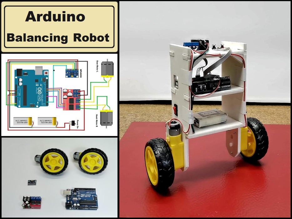
필요한 재료 및 부품
- Arduino Uno: 로봇의 '두뇌' 역할을 하는 마이크로컨트롤러.
- MPU6050 가속도계 및 자이로스코프 센서: 기울기 및 회전 속도 데이터를 측정.
- L298N 모터 드라이버: 모터의 방향과 속도를 제어.
- DC 모터 x 2: 바퀴와 연결된 로봇의 이동 및 균형 유지 장치.
- 바퀴 x 2: DC 모터에 연결되어 로봇 이동 가능.
- 리튬 이온 배터리(충전식): 전원 공급 장치.
1단계: 셀프 밸런싱 로봇 이해하기
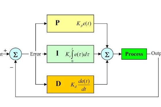
셀프 밸런싱 로봇이란 무엇일까요? 이 로봇은 땅에 떨어지지 않고 스스로 균형을 잡는 데 최적화된 기계입니다. 가속도계와 자이로스코프 센서에서 데이터를 받아, PID(Proportional, Integral, Derivative) 제어를 통해 기울기를 감지하고 바로 잡습니다.
- MPU6050 센서는 중력과 로봇의 방향을 측정.
- PID 알고리즘은 센서 데이터를 처리하고 휠의 속도 및 방향을 조정.
- 이를 통해 로봇이 앞으로 혹은 뒤로 움직이며 균형을 유지합니다.

2단계: 로봇 구성 요소 설명
- MPU6050
- X, Y, Z 축을 따라 기울기 감지.
- 데이터를 Arduino로 전송.
- Arduino Uno
- 센서 데이터를 처리하여 모터 제어 신호 생성.
- L298N 모터 드라이버
- 모터의 방향 및 속도를 제어.
- DC 모터
- 바퀴 속도를 조정하여 로봇의 기울기를 보정.
- 전원 공급
- 두 개의 리튬 이온 배터리를 사용해 시스템 전원 제공.
3단계: 작동 원리 이해하기
- 기본 원리 가속도계는 로봇의 기울기를 측정하고, 자이로스코프는 회전 속도를 감지합니다. 센서 데이터를 PID 알고리즘으로 처리하여 로봇이 넘어지지 않도록 휠의 속도를 실시간으로 조정합니다.
- PID 튜닝
- Kp (비례 게인): 기울기에 따른 초기 반응 조정.
- Kd (미분 게인): 진동을 줄이고 안정화.
- Ki (적분 게인): 시간이 지남에 따라 오차 보정.
4단계: 로봇 제작 및 튜닝
- 프레임 제작 PVC 보드나 다른 가벼운 소재를 사용하여 프레임을 제작합니다.
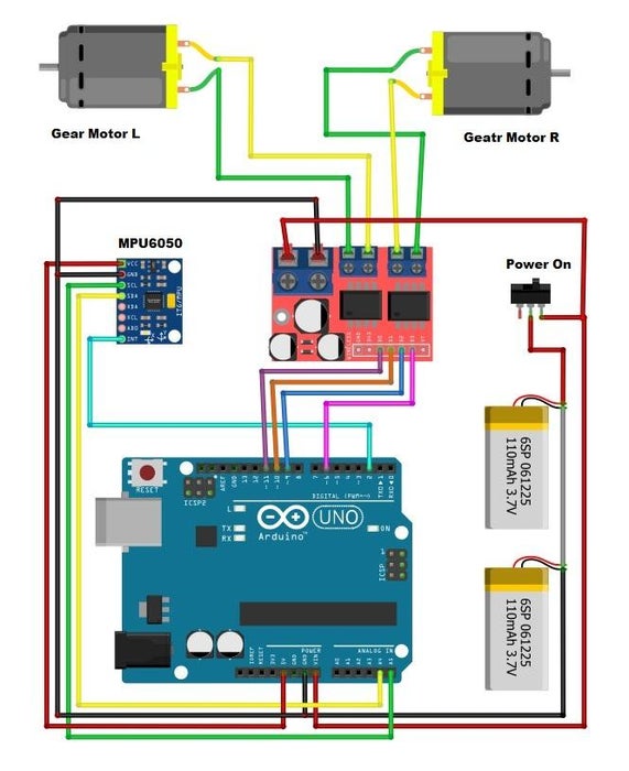
- 센서 및 부품 연결
- MPU6050, Arduino, 모터 드라이버 및 배터리를 조립.
- PID 튜닝 및 테스트
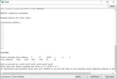
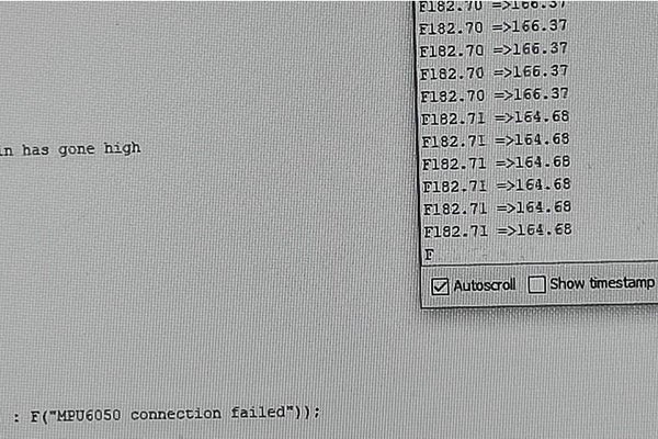
- 직렬 모니터를 이용해 데이터를 확인하고 각 변수(Kp, Kd, Ki)를 설정.
- 최종 조정
- 안정적인 균형을 유지할 수 있도록 테스트하고 필요한 조정을 합니다.
#include "I2Cdev.h"
#include <PID_v1.h> //From https://github.com/br3ttb/Arduino-PID-Library/blob/master/PID_v1.h
#include "MPU6050_6Axis_MotionApps20.h" //https://github.com/jrowberg/i2cdevlib/tree/master/Arduino/MPU6050
MPU6050 mpu;
// MPU control/status vars
bool dmpReady = false; // set true if DMP init was successful
uint8_t mpuIntStatus; // holds actual interrupt status byte from MPU
uint8_t devStatus; // return status after each device operation (0 = success, !0 = error)
uint16_t packetSize; // expected DMP packet size (default is 42 bytes)
uint16_t fifoCount; // count of all bytes currently in FIFO
uint8_t fifoBuffer[64]; // FIFO storage buffer
// orientation/motion vars
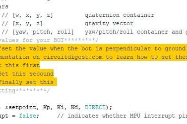
Quaternion q; // [w, x, y, z] quaternion container
VectorFloat gravity; // [x, y, z] gravity vector
float ypr[3]; // [yaw, pitch, roll] yaw/pitch/roll container and gravity vector
/*********Tune these 4 values for your BOT*********/
double setpoint= 182; //set the value when the bot is perpendicular to ground using serial monitor.
//Read the project documentation on circuitdigest.com to learn how to set these values
double Kp = 15; //21 Set this first
double Kd = 0.9; //0.8 Set this secound
double Ki = 140; //140 Finally set this
/******End of values setting*********/
double input, output;
PID pid(&input, &output, &setpoint, Kp, Ki, Kd, DIRECT);
volatile bool mpuInterrupt = false; // indicates whether MPU interrupt pin has gone high
void dmpDataReady()
{
mpuInterrupt = true;
}
void setup() {
Serial.begin(115200);
// initialize device
Serial.println(F("Initializing I2C devices..."));
mpu.initialize();
// verify connection
Serial.println(F("Testing device connections..."));
Serial.println(mpu.testConnection() ? F("MPU6050 connection successful") : F("MPU6050 connection failed"));
// load and configure the DMP
devStatus = mpu.dmpInitialize();
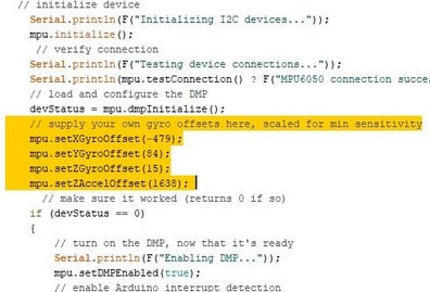
// supply your own gyro offsets here, scaled for min sensitivity
mpu.setXGyroOffset(-479);
mpu.setYGyroOffset(84);
mpu.setZGyroOffset(15);
mpu.setZAccelOffset(1638);
// make sure it worked (returns 0 if so)
if (devStatus == 0)
{
// turn on the DMP, now that it's ready
Serial.println(F("Enabling DMP..."));
mpu.setDMPEnabled(true);
// enable Arduino interrupt detection
Serial.println(F("Enabling interrupt detection (Arduino external interrupt 0)..."));
attachInterrupt(0, dmpDataReady, RISING);
mpuIntStatus = mpu.getIntStatus();
// set our DMP Ready flag so the main loop() function knows it's okay to use it
Serial.println(F("DMP ready! Waiting for first interrupt..."));
dmpReady = true;
// get expected DMP packet size for later comparison
packetSize = mpu.dmpGetFIFOPacketSize();
//setup PID
pid.SetMode(AUTOMATIC);
pid.SetSampleTime(10);
pid.SetOutputLimits(-255, 255);
}
else
{
// ERROR!
// 1 = initial memory load failed
// 2 = DMP configuration updates failed
// (if it's going to break, usually the code will be 1)
Serial.print(F("DMP Initialization failed (code "));
Serial.print(devStatus);
Serial.println(F(")"));
}
//Initialise the Motor outpu pins
pinMode (6, OUTPUT);
pinMode (9, OUTPUT);
pinMode (10, OUTPUT);
pinMode (11, OUTPUT);
//By default turn off both the motors
analogWrite(6,LOW);
analogWrite(9,LOW);
analogWrite(10,LOW);
analogWrite(11,LOW);
}
void loop() {
// if programming failed, don't try to do anything
if (!dmpReady) return;
// wait for MPU interrupt or extra packet(s) available
while (!mpuInterrupt && fifoCount < packetSize)
{
//no mpu data - performing PID calculations and output to motors
pid.Compute();
//Print the value of Input and Output on serial monitor to check how it is working.
Serial.print(input); Serial.print(" =>"); Serial.println(output);
if (input>150 && input<200){//If the Bot is falling
if (output>0) //Falling towards front
Forward(); //Rotate the wheels forward
else if (output<0) //Falling towards back
Reverse(); //Rotate the wheels backward
}
else //If Bot not falling
Stop(); //Hold the wheels still
}
// reset interrupt flag and get INT_STATUS byte
mpuInterrupt = false;
mpuIntStatus = mpu.getIntStatus();
// get current FIFO count
fifoCount = mpu.getFIFOCount();
// check for overflow (this should never happen unless our code is too inefficient)
if ((mpuIntStatus & 0x10) || fifoCount == 1024)
{
// reset so we can continue cleanly
mpu.resetFIFO();
Serial.println(F("FIFO overflow!"));
// otherwise, check for DMP data ready interrupt (this should happen frequently)
}
else if (mpuIntStatus & 0x02)
{
// wait for correct available data length, should be a VERY short wait
while (fifoCount < packetSize) fifoCount = mpu.getFIFOCount();
// read a packet from FIFO
mpu.getFIFOBytes(fifoBuffer, packetSize);
// track FIFO count here in case there is > 1 packet available
// (this lets us immediately read more without waiting for an interrupt)
fifoCount -= packetSize;
mpu.dmpGetQuaternion(&q, fifoBuffer); //get value for q
mpu.dmpGetGravity(&gravity, &q); //get value for gravity
mpu.dmpGetYawPitchRoll(ypr, &q, &gravity); //get value for ypr
input = ypr[1] * 180/M_PI + 180;
}
}
void Forward() //Code to rotate the wheel forward
{
analogWrite(6,output);
analogWrite(9,0);
analogWrite(10,output);
analogWrite(11,0);
Serial.print("F"); //Debugging information
}
void Reverse() //Code to rotate the wheel Backward
{
analogWrite(6,0);
analogWrite(9,output*-1);
analogWrite(10,0);
analogWrite(11,output*-1);
Serial.print("R");
}
void Stop() //Code to stop both the wheels
{
analogWrite(6,0);
analogWrite(9,0);
analogWrite(10,0);
analogWrite(11,0);
Serial.print("S");
}결론
이 프로젝트는 단순히 로봇을 만드는 것을 넘어 물리, 전자공학 및 소프트웨어에 대한 실용적인 이해를 높이는 데 큰 도움이 됩니다. PID 제어를 사용한 센서 기반 로봇은 흥미로우면서도 배우는 기쁨을 주는 결과를 선사합니다. 오늘 도전해 보세요! 🤖✨
728x90
반응형
'로봇프로젝트' 카테고리의 다른 글
| Arduino를 사용하여 집에서 인간 추적 로봇을 만드는 방법 (2) | 2024.12.06 |
|---|---|
| 태양열 장애물 회피 자동차 (3) | 2024.11.01 |
| 아두이노를 이용한 자가 연주 우쿨렐레 로봇 (0) | 2024.09.19 |
| DC 모터를 사용하는 Doodlebot (1) | 2024.09.03 |
| 체이스 탱크 로봇 만들기 (0) | 2023.12.11 |


